Exposed & Interlaced – Exploring Motion in Analog and Digital
Spring 2017
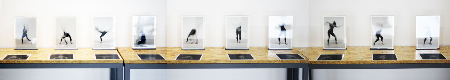
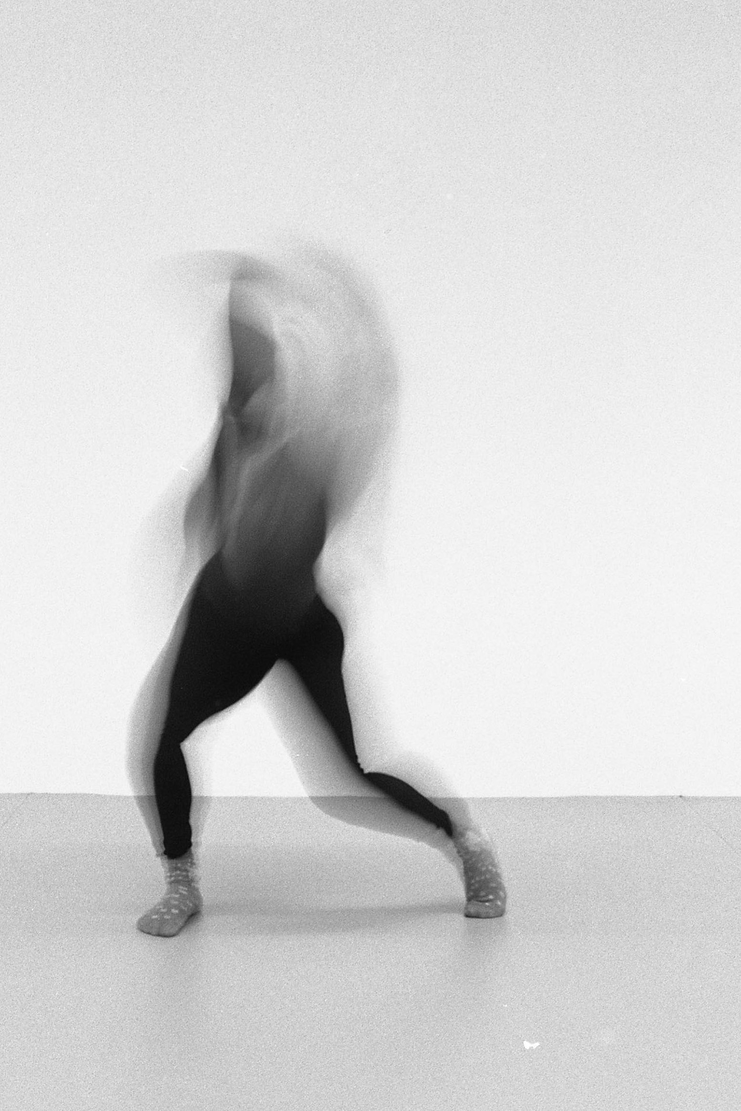
Exposed & Interlaced – Exploring Motion in Analog and Digital is a sequence of imaging chronicling a dance performance into 10 different fragments. The viewer is able to view each fragment as a long exposure film print, as a representation of analog means, and an interactive lenticular that allows the viewer to see a short video clip by changing their perspective, as a representation of digital means. The fragments are displayed sequentially to communicate the entire dance performance.
Skip to DIY Motion Lenticular Tutorial
Conceptual Development:
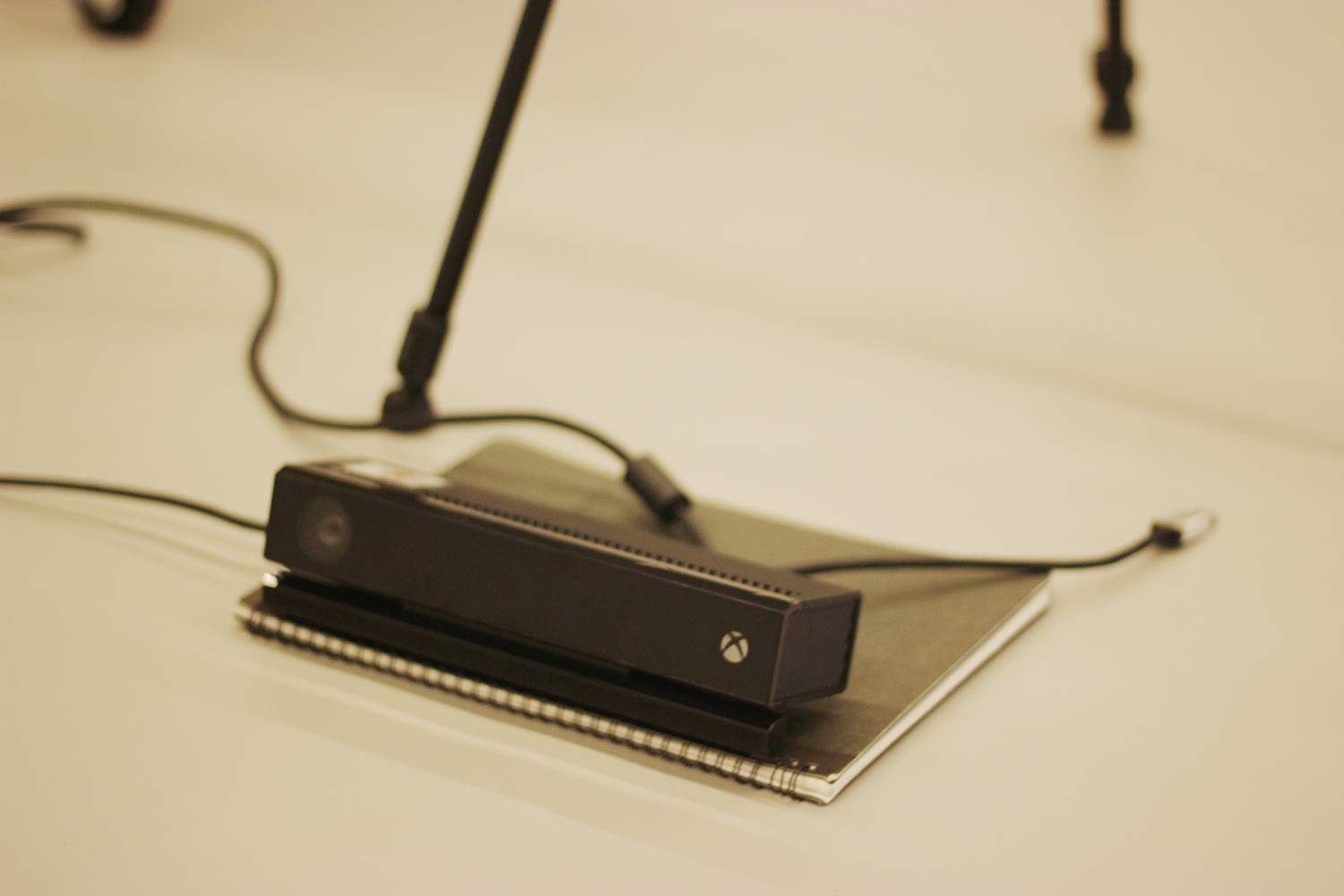
This idea was formed with my own experiences here at NYU Shanghai and also when I studied abroad. I took the Intro to Film Photography class in NYU Prague with the great artist/Professor Bara Mrazkova. I loved every second of the class and also the time I got to spend in the darkroom, the unexpected surprises along with the special personality of the film, and the delicate nuance. I also took a class with Professor Moon last semester at NYU Shanghai called Kinetic Interfaces, where I had the chance to experiment with Microsoft Kinect, a motion sensing device and the body movement data. For the final project of that class, I did a dance collaboration with my friend Ann. I was pretty amazed by how the human body was recognized and captured.
I had this idea of doing human size photogram to show the human movement. According to Wikipedia, “a photogram is a photographic image made without a camera by placing objects directly onto the surface of a light-sensitive material such as photographic paper and then exposing it to light. The usual result is a negative shadow image that shows variations in tone that depends upon the transparency of the objects used. Areas of the paper that have received no light appear white; those exposed through transparent or semi-transparent objects appear gray” (https://en.wikipedia.org/wiki/Photogram). Then I found a photographic artist Floris Neusüss who did human size photograms (http://www.vonlintel.com/Floris-Neususs.html). I contacted the gallery inquiring about the process and materials and I heard back from them with the answers I needed. However, given the fact that this idea has a really strict requirement on the space, a darkroom with enough space with a big enough pool/bathtub for developing prints, and also the materials, customized size/unusual big size photo papers, which would potentially elevate the cost of the project by a fairly large amount as well as the time consumption. I decided to pivot it.
Instead of analog media taking up the entire project, I thought it would be a good idea to bring digital into the field. Kinect can sense and record body motion data in digital form, and film photography is an analog way to record things. I started paying attention to the contrast and different between these two means. Although we live in an analog world, almost every single aspect has been heavily digitized. When you go to a concert, you see a wall of iPhones screen lit up; when you go to a museum, you see people with lenses capturing people striking poses with the art works; people read pdfs; etc. Almost all the analog media have at least one or multiple replacements that feature convenience on user’s side when it comes to distribution, utilization and manipulation.
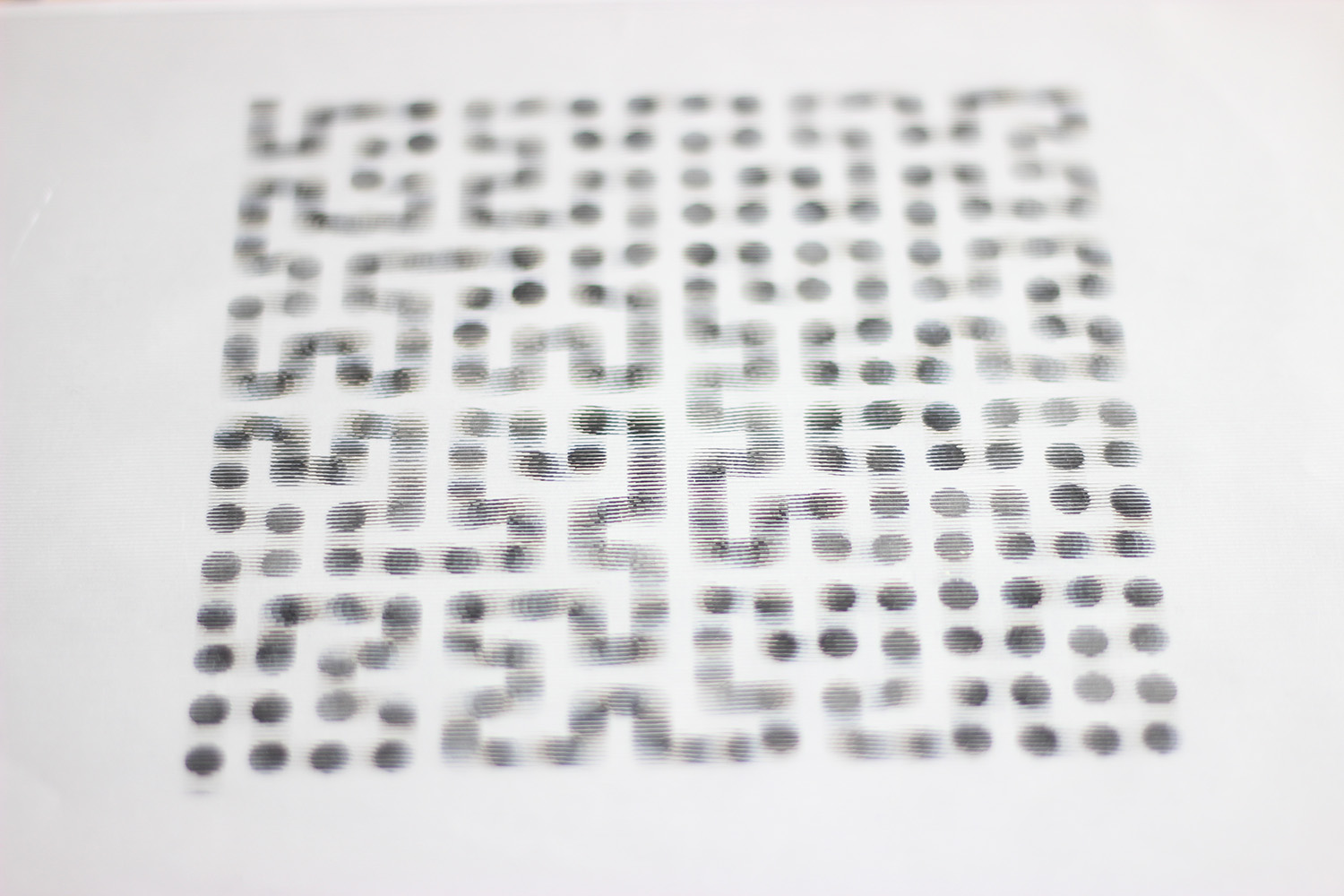
Having dance as the as the content that shared by digital and analog approach of data recording, I started looking for media for presenting the data. AJ introduced lenticular and gifpop to me. Lenticular printing is a technology in which lenticular lenses (a technology that is also used for 3D displays) are used to produce printed images with an illusion of depth, or the ability to change or move as the image is viewed from different angles. I thought this would be a good way to present digital data which essentially is a short snippet of the dance piece and that data is in point-cloud form since digital recorded data can be easily modified and that directly shows how the Kinect device is sensing and selecting the samples, which is those dots where infrared light it emits lands. Same snippet of dance piece was also recorded on a long-exposed negative. After developing the negative, I printed it out with an enlarger onto a light-sensitive photo paper. Each fragment of the dance piece has two presentations with one being long-exposure film print and one being point cloud lenticular sheet, and in total 10 fragments will be displayed sequentially to communicate the entire dance performance.
The idea of this project is a culmination of my skill set as I am applying the film photography techniques I learned in Prague with the Kinect motion sensing skills I learned in IMA. A wholly original concept, this project dares to mix means of media that haven’t been mixed before and is an opportunity for me to contribute to the fields of work I have always admired in motion capture, film photography, and performance based art, while starting quality documentation in areas that have been ill documented, like lenticular printing.
Technical Development:
Lenticular Effects
Since I had experience with film photography before, I was pretty confident the analog output of this project would not be a challenge compared to making lenticular sheet. I started off with doing research on lenticular techniques. Here’s the general procedure I summarized: order lenticular sheet, pitch testing, interlace images, print, lamination (please go to the end of this post for a more detailed DIY lenticular tutorial). Lenticular technique has a couple of effects – flip, 3D, morph, and motion. Flip makes an image flip from one image to the next. 3D effect creates depth on a normally flat surface. The 3D Effect effect is generated by splicing several frames together to trick the viewer into seeing the 3D effect. Morph effects gradually change one image to another image through the use of sophisticated image algorithms. Motion effect uses multiple frames of an action to show movement from the beginning to the end. In my case, motion would be the effect I need.
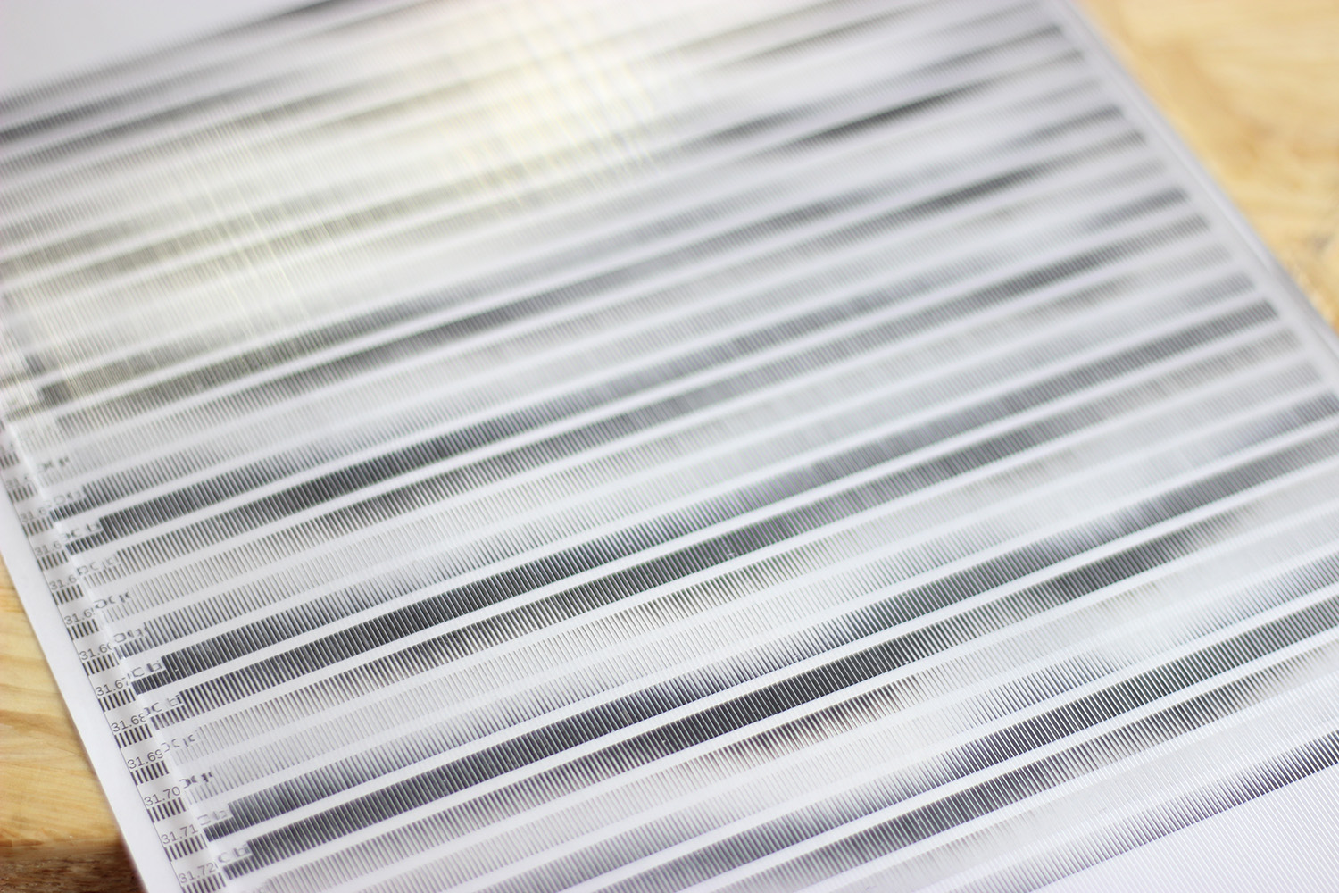
Pitch Test
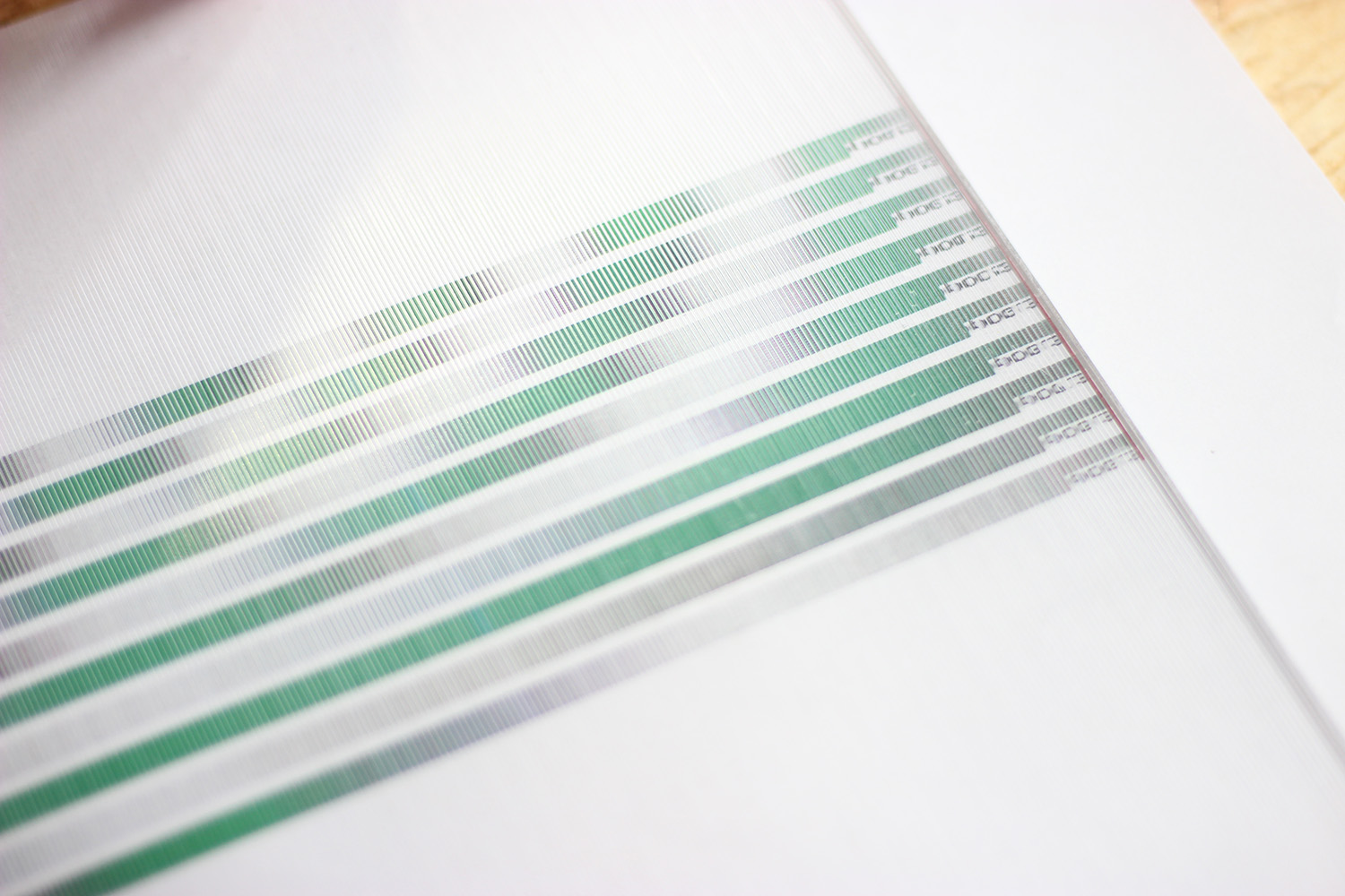
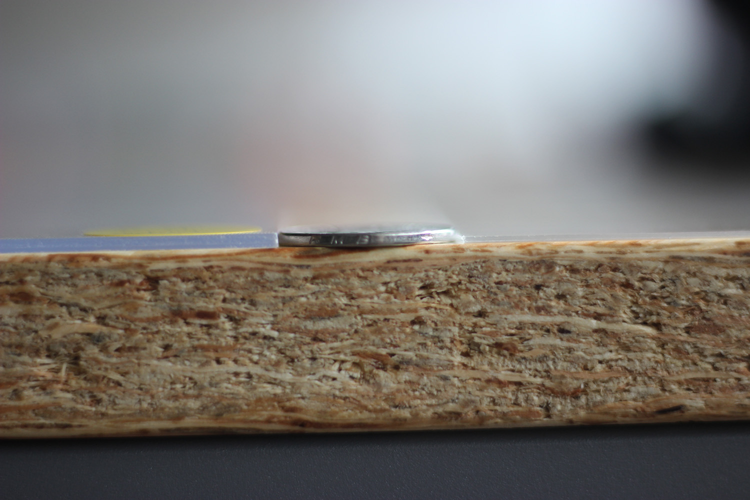
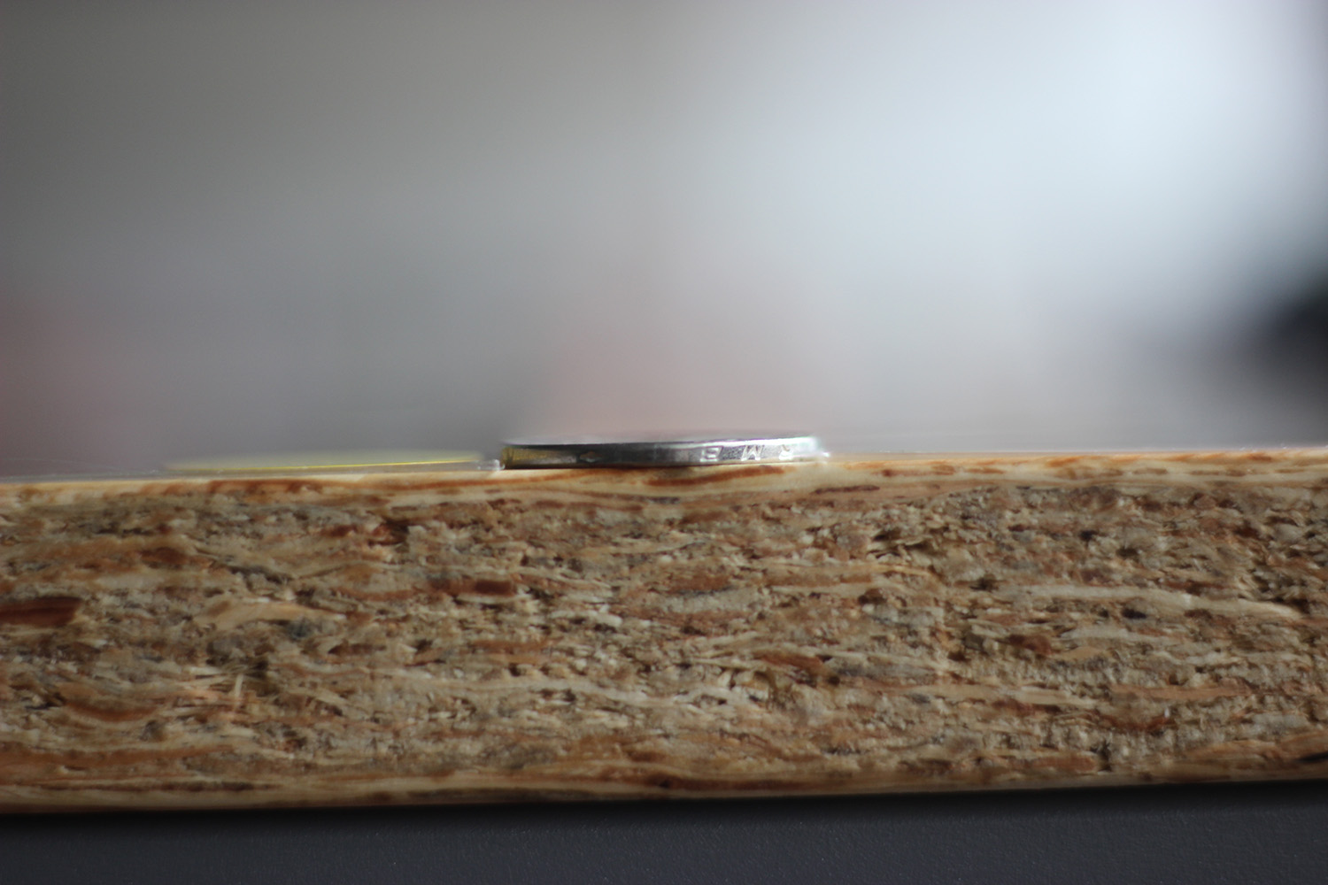
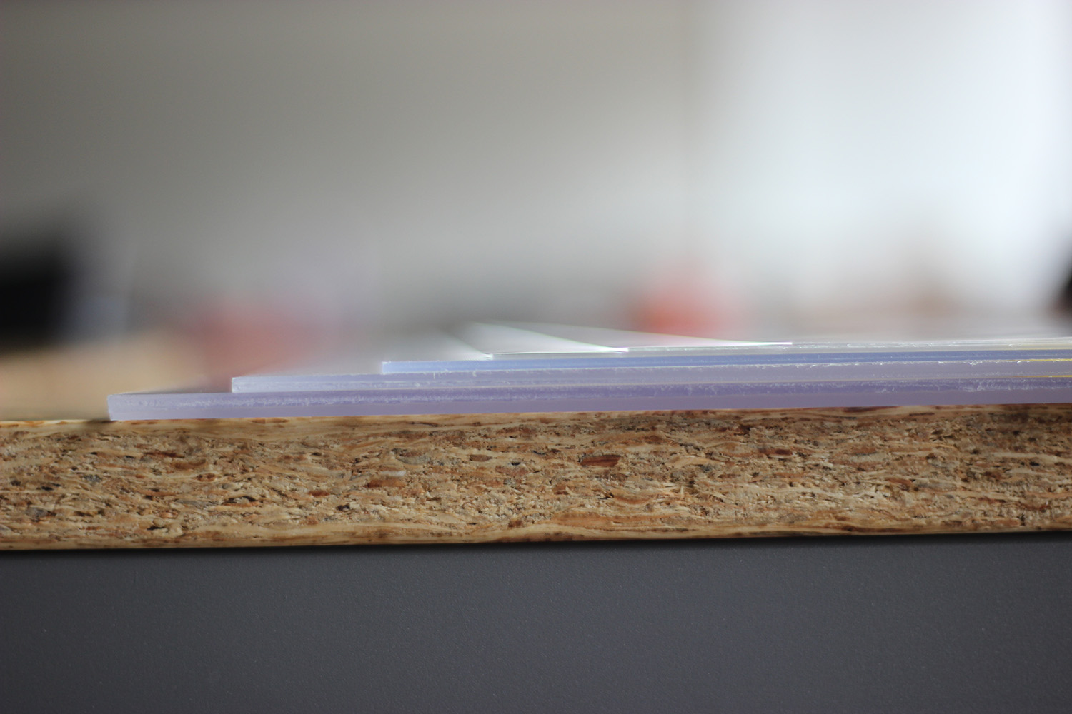
Making lenticular sheet relies heavily on a good printer. The school printer has the maximum of 1200 DPI. Lenticular sheet has one configuration which is LPI (lenticules per inch). Since the images have to be interlaced, the number of frames of images being used multiples LPI of the lenticular sheet should be no more than the maximum DPI of a printer. I started with purchasing lenticular sheets with a relatively low LPI, 25 and 32 from this store. After I received them, I realized they might be too thick for a lenticular sheet, but it could be a good testing round. I did pitch testing, which is essentially a calibration tool. It calibrates the printer, media and lenticular sheet used for a particular image. The purpose of the pitch test is to determine which LPI pitch matches the particular printer/media/lenticular sheet combination. Since output devices may have slight differences in variability, pitch test is needed on each output device you intend to print interlaced images to. Shift your viewing angle left and right. Look at each bar and determine which bar gives you the widest flip from solid black to white across the entire width of the printed area. The bar that represents the best (widest) flip is the proper LPI that you need to interlace your files to.
25, 32, 50, 70, 75, 100 LPI
It turned out that the 32 LPI was actually 31.56 LPI. I decided to make a lenticular testing with a gif I found online to test the motion effect.
25 LPI VS 32 LPI
GIF credit: Bryce Summers, CMU Undergraduate studying Computer Science
It worked. Since its a low LPI lenticular lens, the interlace lines/gaps are pretty obvious though.
Bryce Summers’ GIF with a 32 LPI lenticular lens
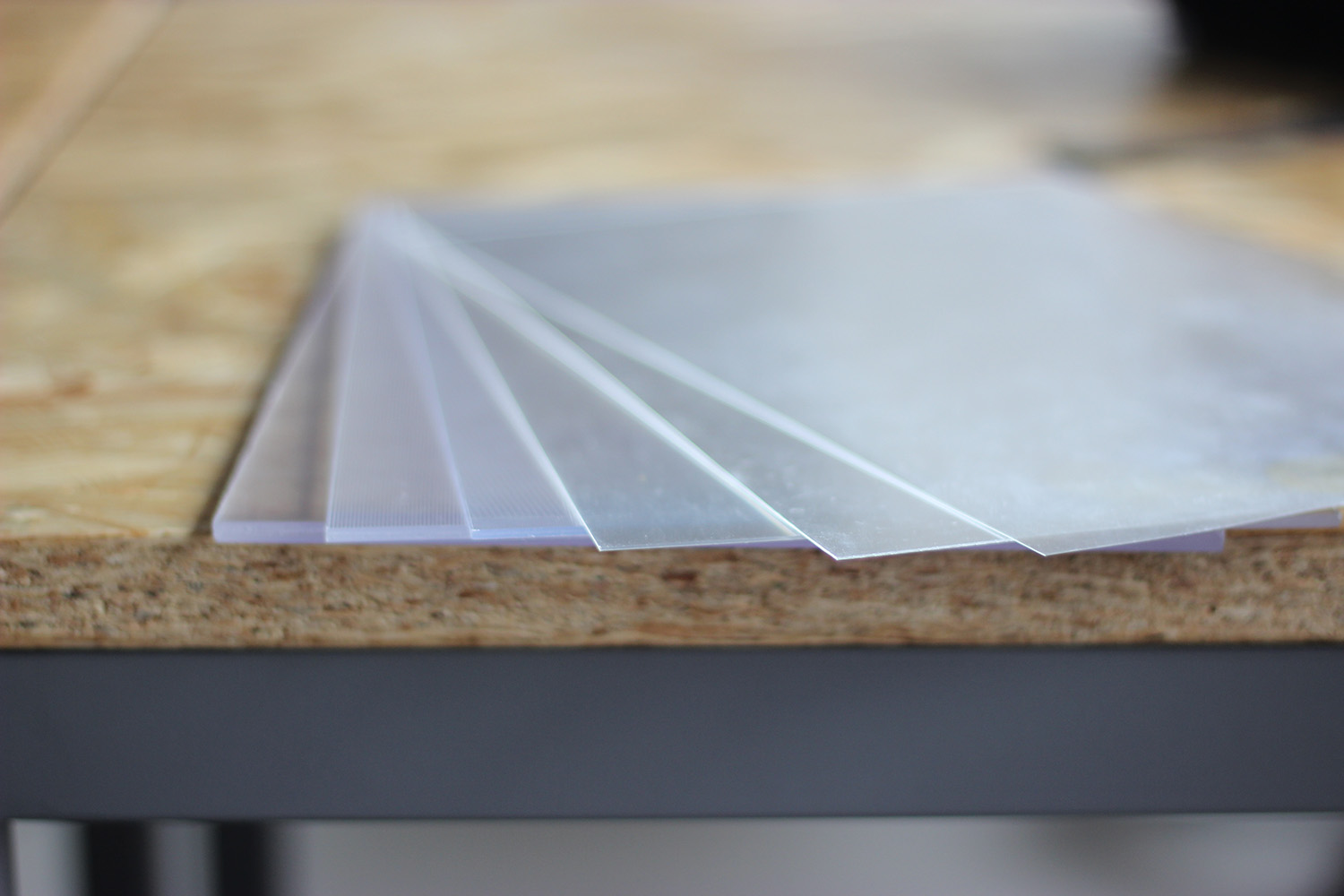
Then I purchased more to test out 50 70 75 100 LPI lenticular lens.
50 LPI VS 70 LPI
75 LPI VS 100 LPI
Among these four, it was sort of impossible to figure out the pitch testing for 100. For 50, 70 and 75 LPI, the actual LPI I got was 50.17, 70.23 and 75.30.
Bryce Summers’ GIF with a 70 LPI lenticular lens
25, 32, 50, 70, 75, 100 LPI
25, 32, 50, 70, 75, 100 LPI
After taking into consideration the thickness, resolution, pitch test result and smoothness of the motion effect, I decided to go with 70 LPI lenticular lens.
Point Cloud VS Color
I was trying to decide what sort of data visualization to show on a lenticular print, and someone told to apply colors of the specific infrared landing points captured by the normal camera in Kinect. I decided t it a try the video above shows how it turned out. I didn’t continue with this for two reasons with first being it didn’t look good, and the second, point cloud represents the essential sampling step in digital data processing. If I had to show color, a better camera would actually give me a better imaging of the dance movement movie with better color and resolution. It makes more sense to show point cloud with a lenticular lens.
NYU Shanghai Default Printing Paper VS 200g/250g Laser Printing Paper
200 & 250g laser printing paper with NYU Shanghai 8F printer
I tried to used different paper because based on my research, a better paper might make the effect smoother. However, the testing with 200g & 250g laser printing paper was a disaster. Although according to maximum of 300g paper.
I suspect that the ink wasn’t dry enough so it looked ruined. In normal cases, a high DPI ink printer would be better than a laser printer in lenticular printing. Thus I decided to stick with the NYU shanghai default printing paper.
Black Point Cloud VS White Point Cloud
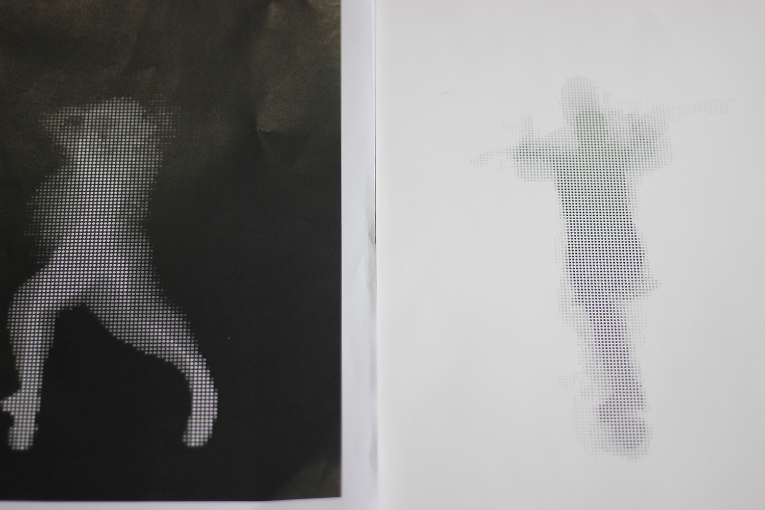
Black point cloud VS white point cloud
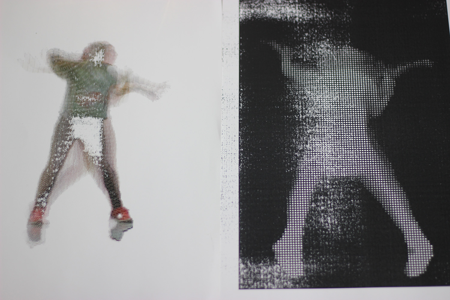
White point cloud on dark background
Black point cloud on white background
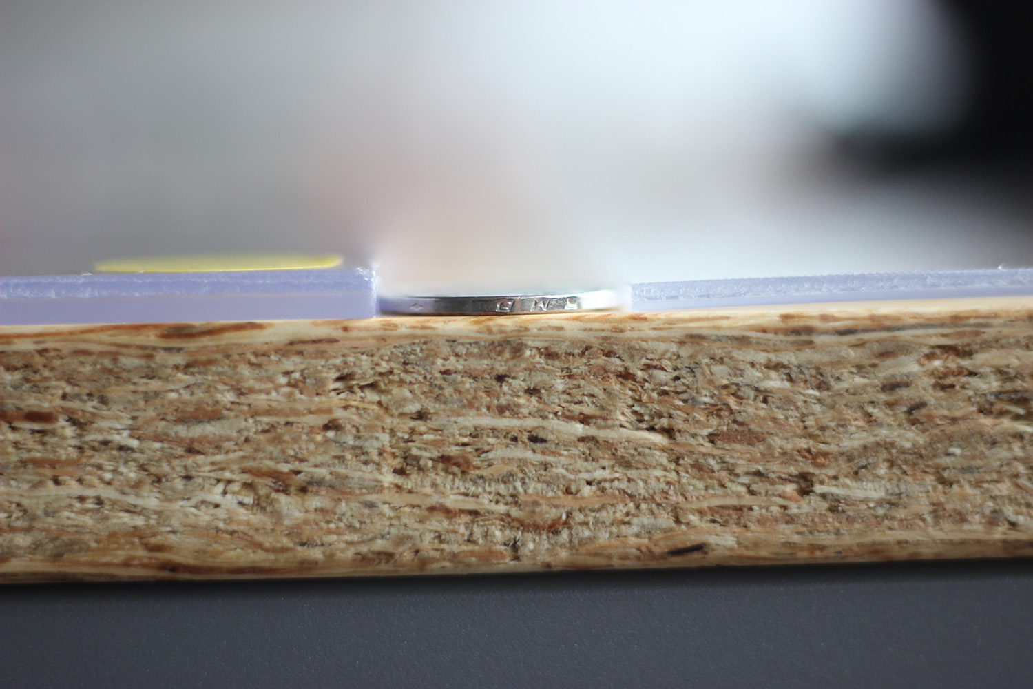
Lamination
The basic procedure is to laminate paper to adhesive and then laminate them to lenticular lens. When laminate adhesive, I peeled half off, and laminate, then do the other half, this can decrease the annoying bubbles that always appear in the lamination process. Please see this tutorial video for further instructions.
Filming
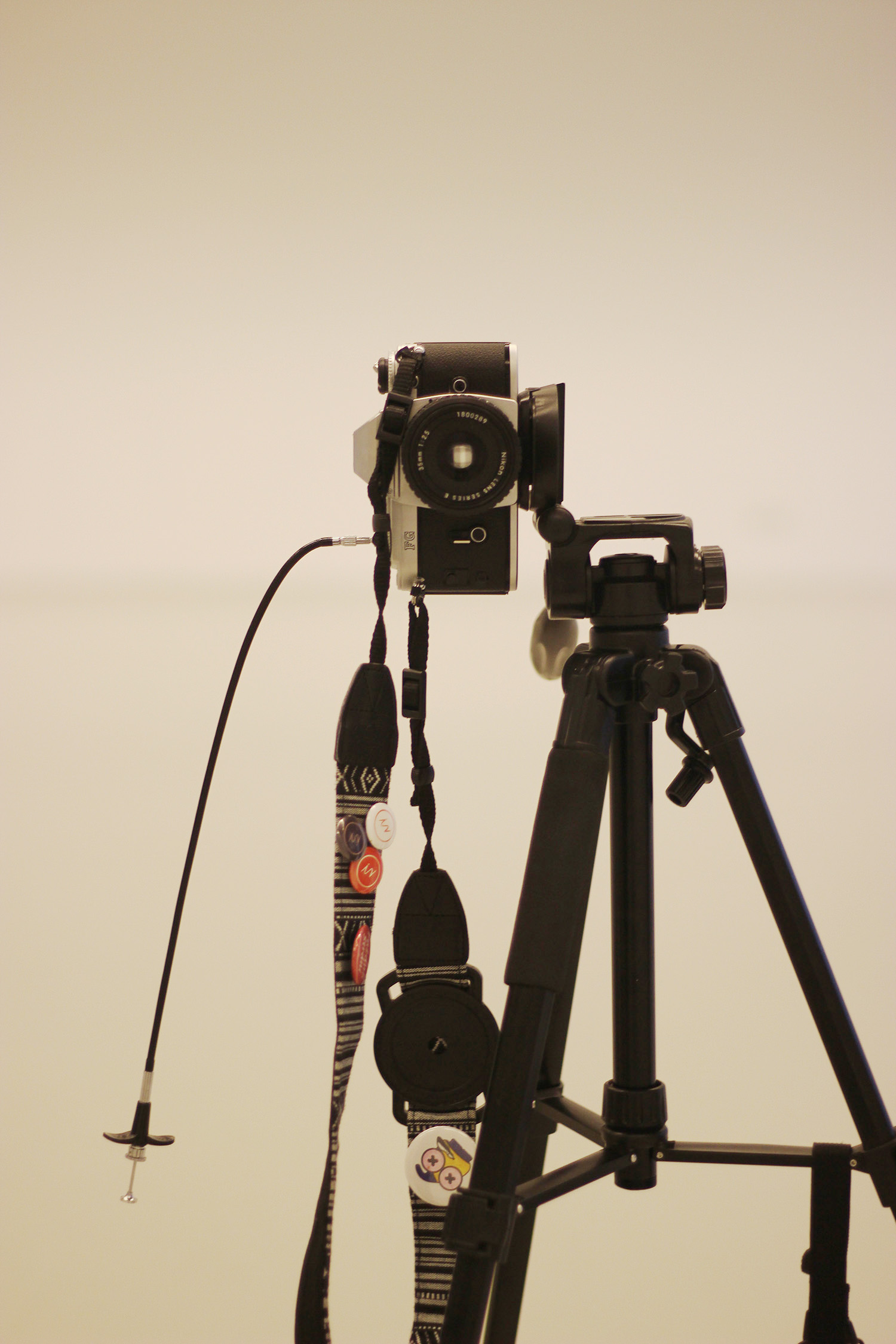
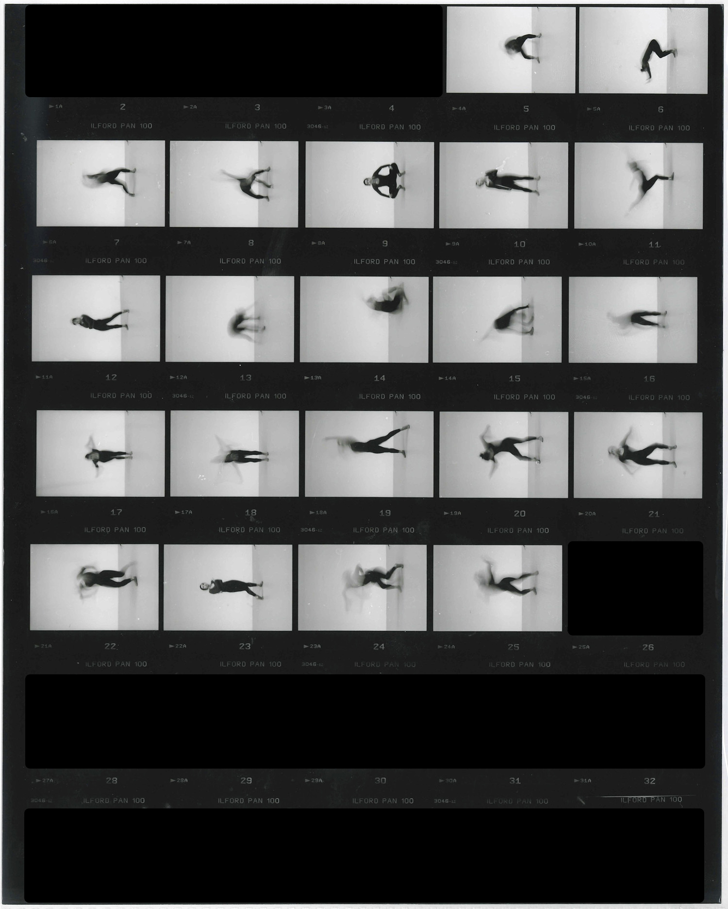
Kinect + film camera on a tripod. I took 20 long-exposure (half second only) photos with the film camera, while recording 20 snippets of the dance performance with each being 25 frames (only 15 was selected). Framerate of the program was around 30 fps, so 15 frames would match what the camera captured.
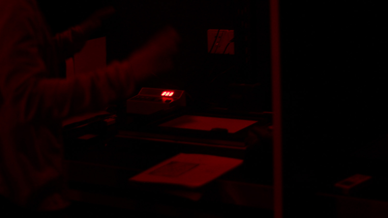
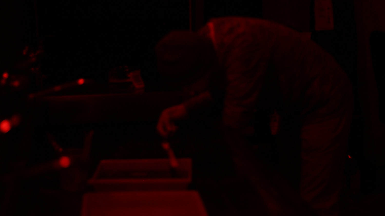
Developing Negatives and Printing Photos
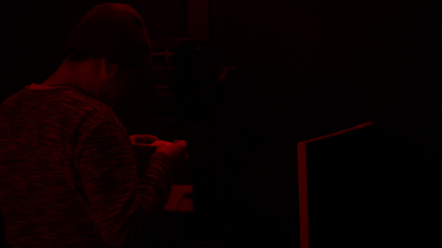
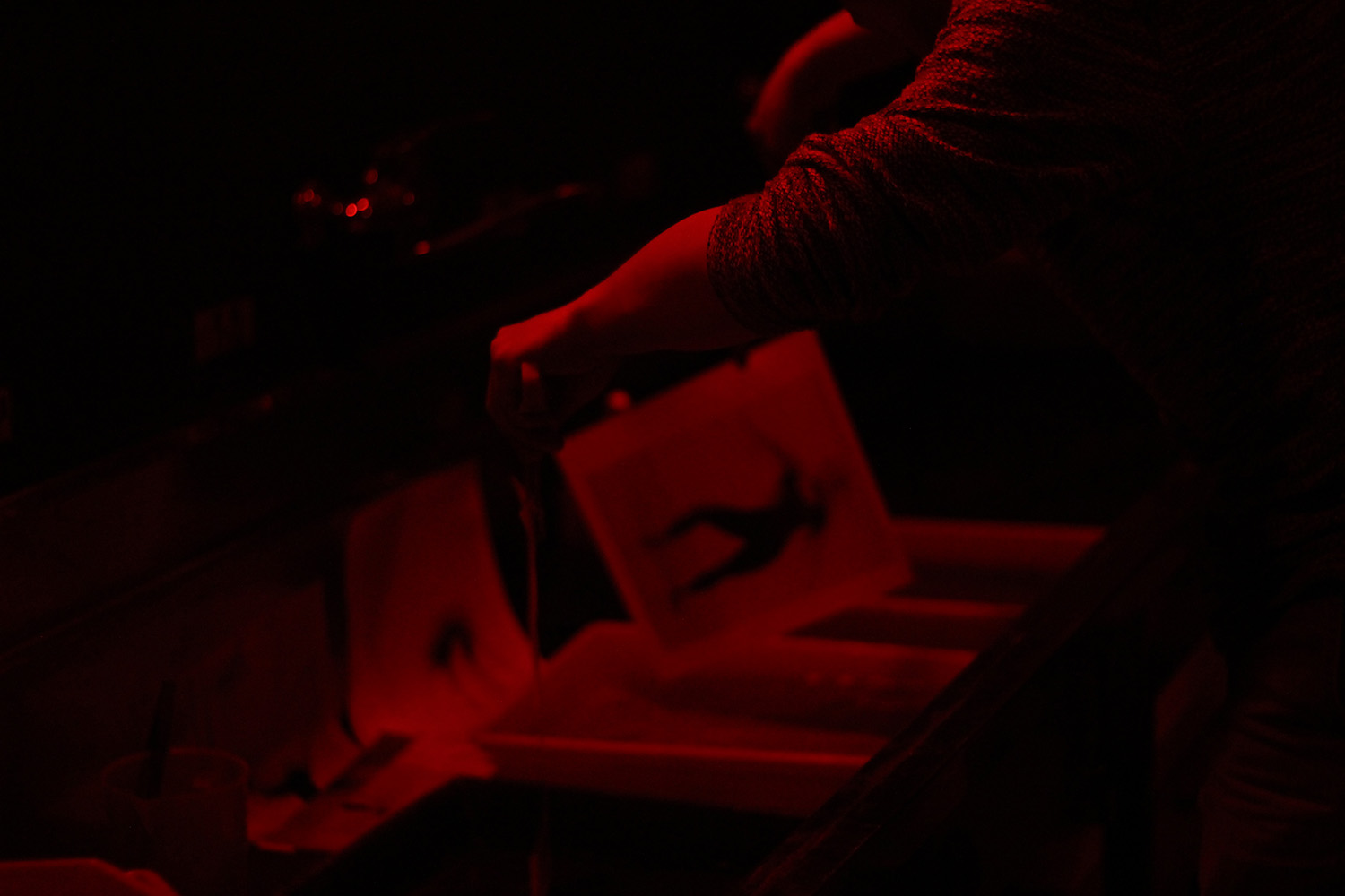
After movement was recorded with both methods, I went to the DN Darkroom in M50 to develop my negatives and printed the photos out.
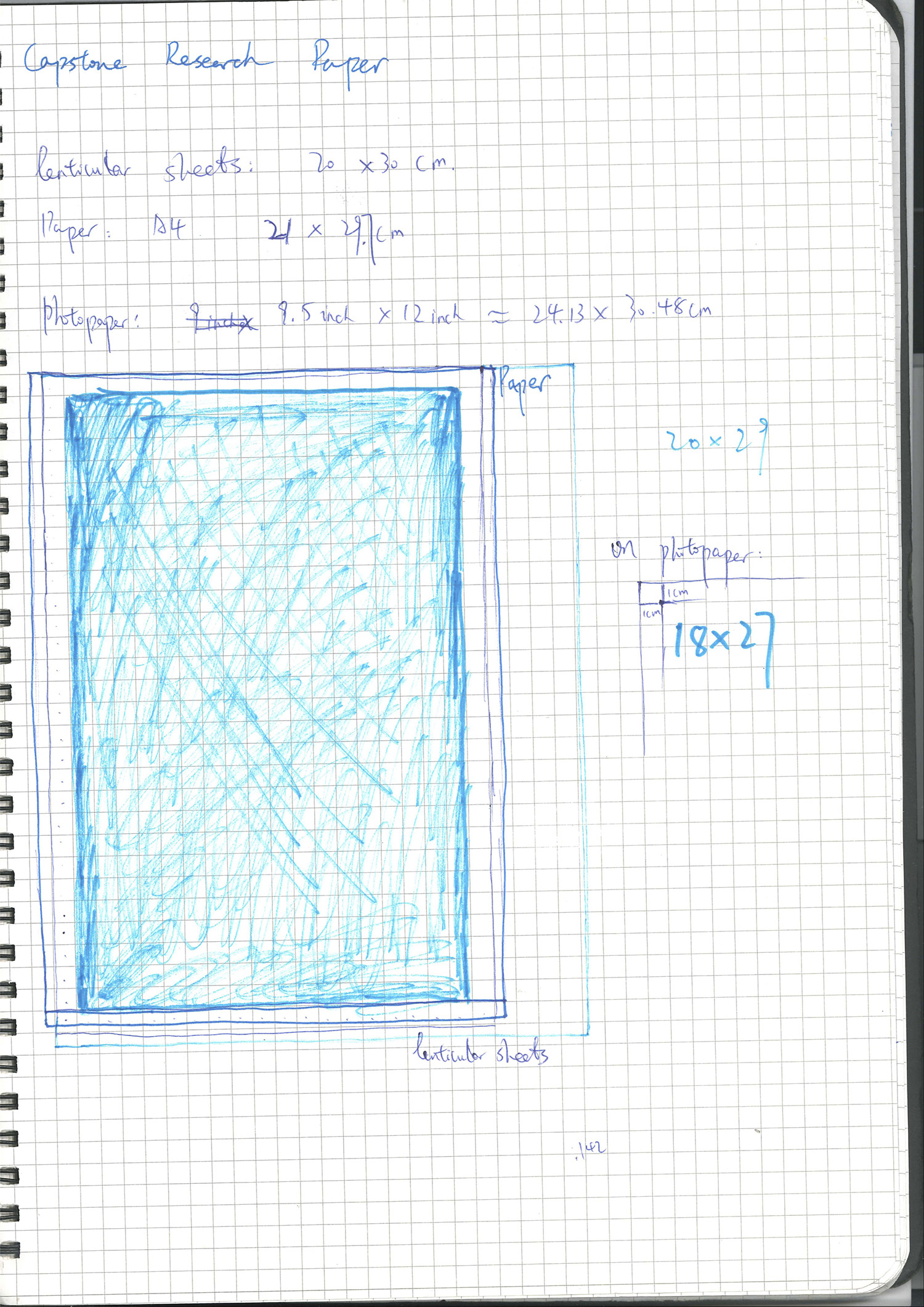
A sketch of unifying sizes of point cloud prints(A4), lenticular lenses(20cm*30cm), and light sensitive photopaper(9.5*12 inches)
I decided to make the final size for both film photographs and lenticular prints to be 18*27cm which involved paper cutter and laser cutter(for lenticular lenses).
Kinect captured point cloud
Acknowledgement
Lenticular printing explained - part 1
CREATING AND USING A PITCH TEST
4 Easy Steps To Making Old-Fashioned Lenticular Images From Your Photos
Creating lenticular images with motion effect
I would like to thank all the following people for helping with my Capstone Project:
Professors: Scott Fitzgerald, Anna Greenspan, Dan Mikesell, JH Moon, Sakar Pudasaini and Clay Shirky
IMA Fellows:AJ, Marcela and Kyle
Dancer: Ann F. Yang
Feedback and filming: Richard Lewei Huang, Tyler Rhorick and Jingyi Sun
Funding support: NYU Shanghai Capstone Team
DIY Motion Lenticular Tutorial
Order Lenticular Sheets
-
Lenticular sheets vary from 10LPI to more than 100LPI. Choose the correct LPI is the key step before making lenticular prints. Smaller LPI lenses have clear/obvious lines which can be distracting or make the image motion effect seem less smooth. 50-75 is a good range for motion lenticular. If the LPI above 75, a high DPI ink printer is recommended, and pitch testing is pretty difficult to conduct when you DIY.
-
Make sure: LPI * number of frames <= Highest DPI on your printer
-
I order my lenticular sheets from this place. Good/helpful service if you speak Chinese. They have a wide range of lenticular lens with different LPIs. The normal ones they sell is 20cm * 30cm, but you can choose the orientation of the lenticules. I picked horizontal lenticules (20cm) because my prints are vertical.
-
Make sure you buy their glue/adhesive sheet too
-
I have 25, 32, 50, 70, 75, 100 six configurations with vertical/horizontal orientations, if you wanna experiment with them, feel free to come to me.
Pitch Testing
-
Just like some Taobao vendors, lenticular sheets they sell can not really be trusted as well. 25 LPI can actually be 25.23, and 75 LPI can actually be 75.123. Each lens LPI might vary even if you order them a bunch with the same configuration.
-
Pitch testing is REALLY REALLY IMPORTANT! An accurate pitch can make the motion effect more smooth.
-
This is the place where I downloaded my pitch testing sheet generator. The Mac one didn’t work for me, so I had to use a PC/Wine on Mac to generate pitch testing sheet.
-
Three to four rounds of pitch testing is necessary for a lens to get as accurate as possible(ie. xx.xx). For example, for a 70 LPI lens, I would do 70.00-70.10,-70.20-…-72 first, then 70.00-70.03-70.06- … – 70.60, then 70.10-70.11-70.12- … – 70.30. For each round, the range is getting smaller, also the step is getting smaller too.
-
Make sure your print resolution matches your printer DPI.
-
Put the printed pitch test sheet under the lenticular screen. You can see the similar picture:
-
Close one eye and turn the head to the left, and then to the right. Look at the moire moving. Among the strips there are two strips where moire runs TOWARDS each other: the top moire moves from left to right, the bottom one moves from right to left (or otherwise). These two strips are close to the necessary strip.
-
The pitch of the strip that is the most continuous(fullest black or white) is close to the lenticular sheet pitch.
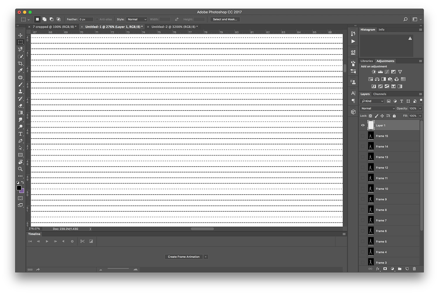
Interlacing Images (record action in photoshop recommended for mass reproduction)
-
After pitch test, it is time to bring out the good ol’ pal, Photoshop
-
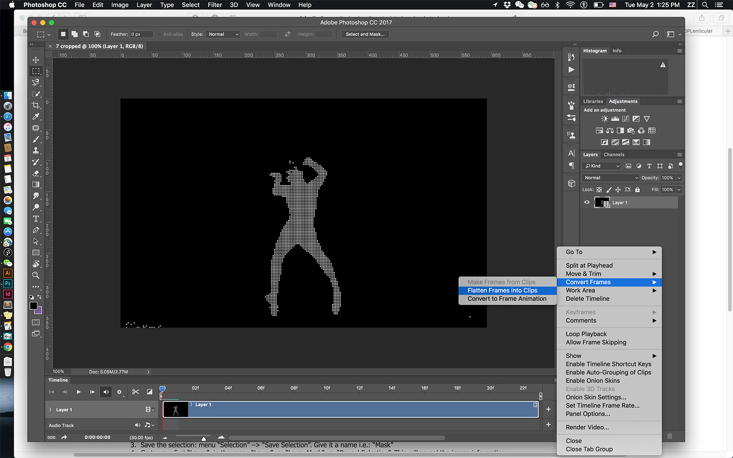
Import video/gif, and convert them to frames
-
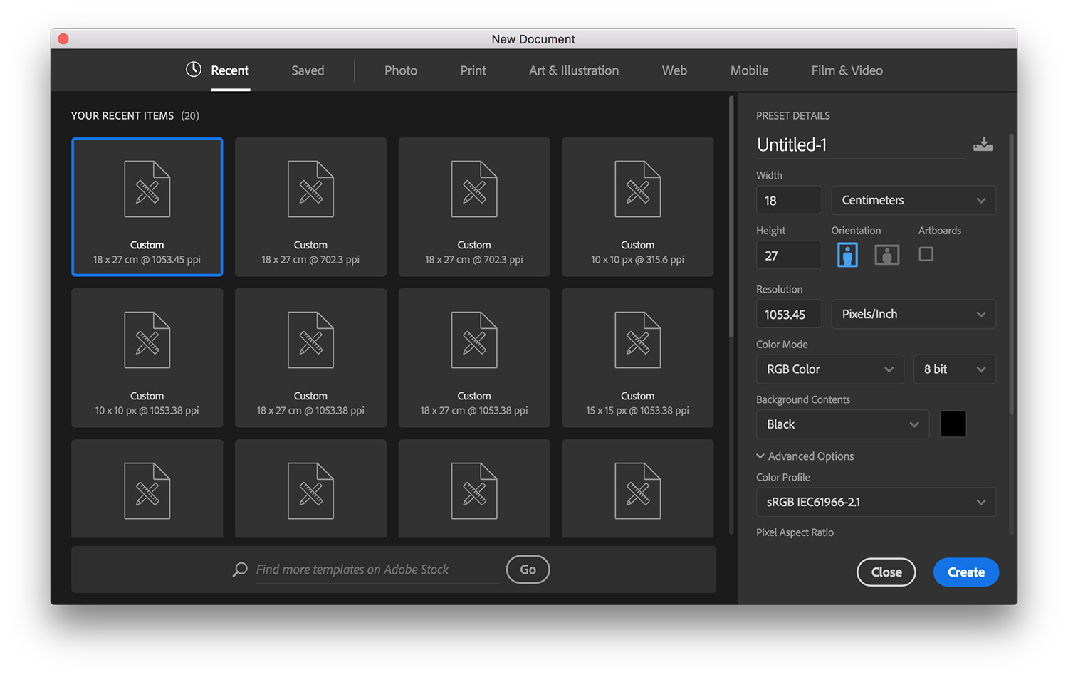
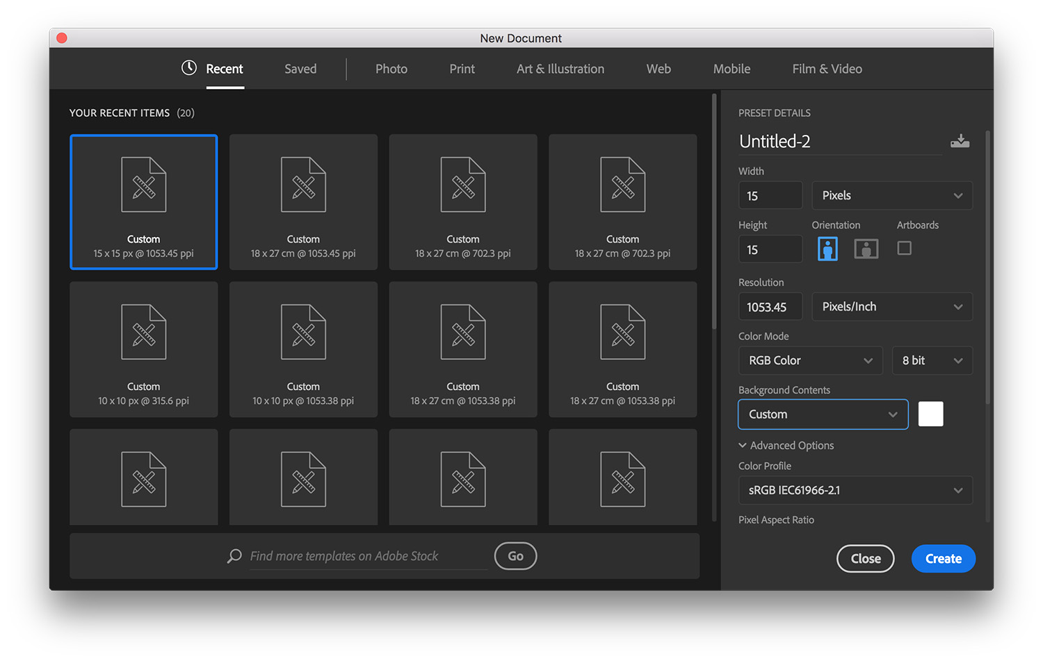
Create a new file with final printing size(including bleed)
-
Set the resolution to be LPI x frames (in my case, 70.23 x 15 = 1053.45)
-
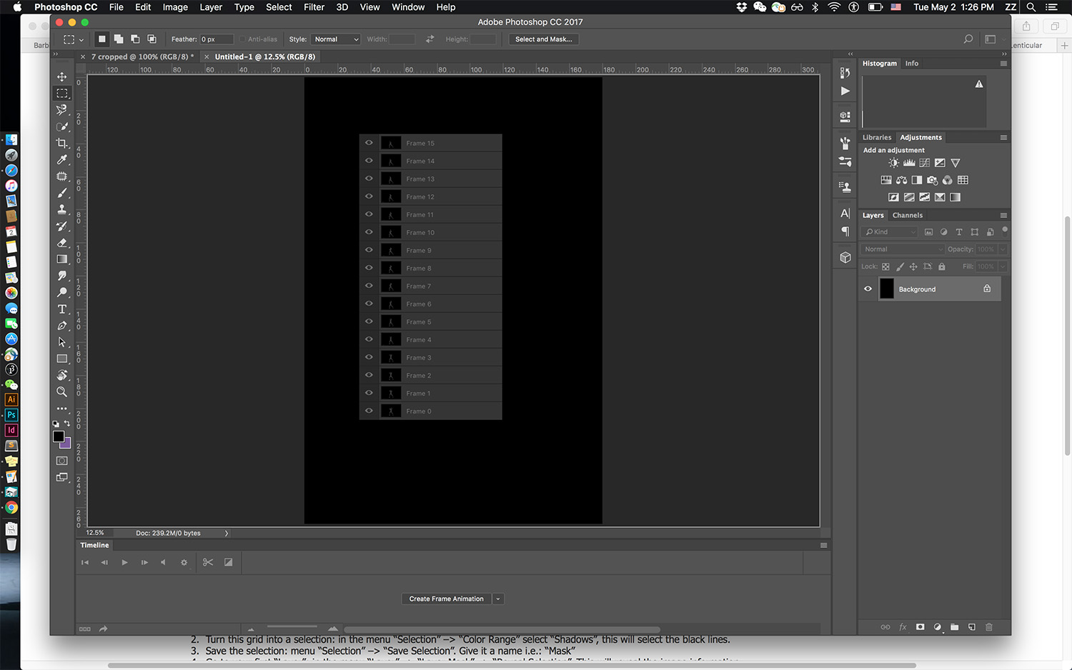
Select frames you need from the video/gif file
-
Drag them onto the final printing file
-
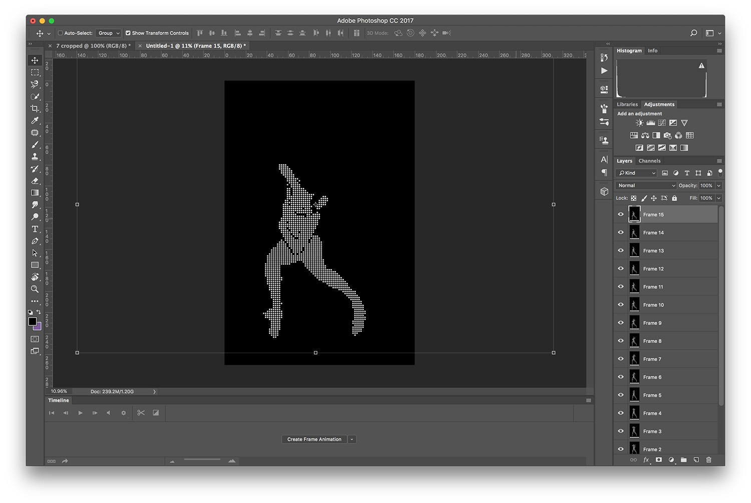
Scale and position those frames
-
Make sure each frame is correctly positioned and the content is within the border
8 Create a new file from the menu<
- Set the “Width” and “Height” to Y pixels (Y = the number of images you are interlacing, in my case 15 pixels x 15 pixels). Set the resolution to LPI x frames. In my case, 70.23 x 15 = 1053.45.
-
Zoom to the maximum and use the selection tool (“Marquee tool”), select one pixel line or column (horizontal is better for flip and vertical is mandatory for 3D, in my case horizontal line with one pixel height selected)
-
Fill this selection in black: in the menu bar go to: “Edit”–> ”Fill” and select “Black” from the “Content” dropdown menu
-
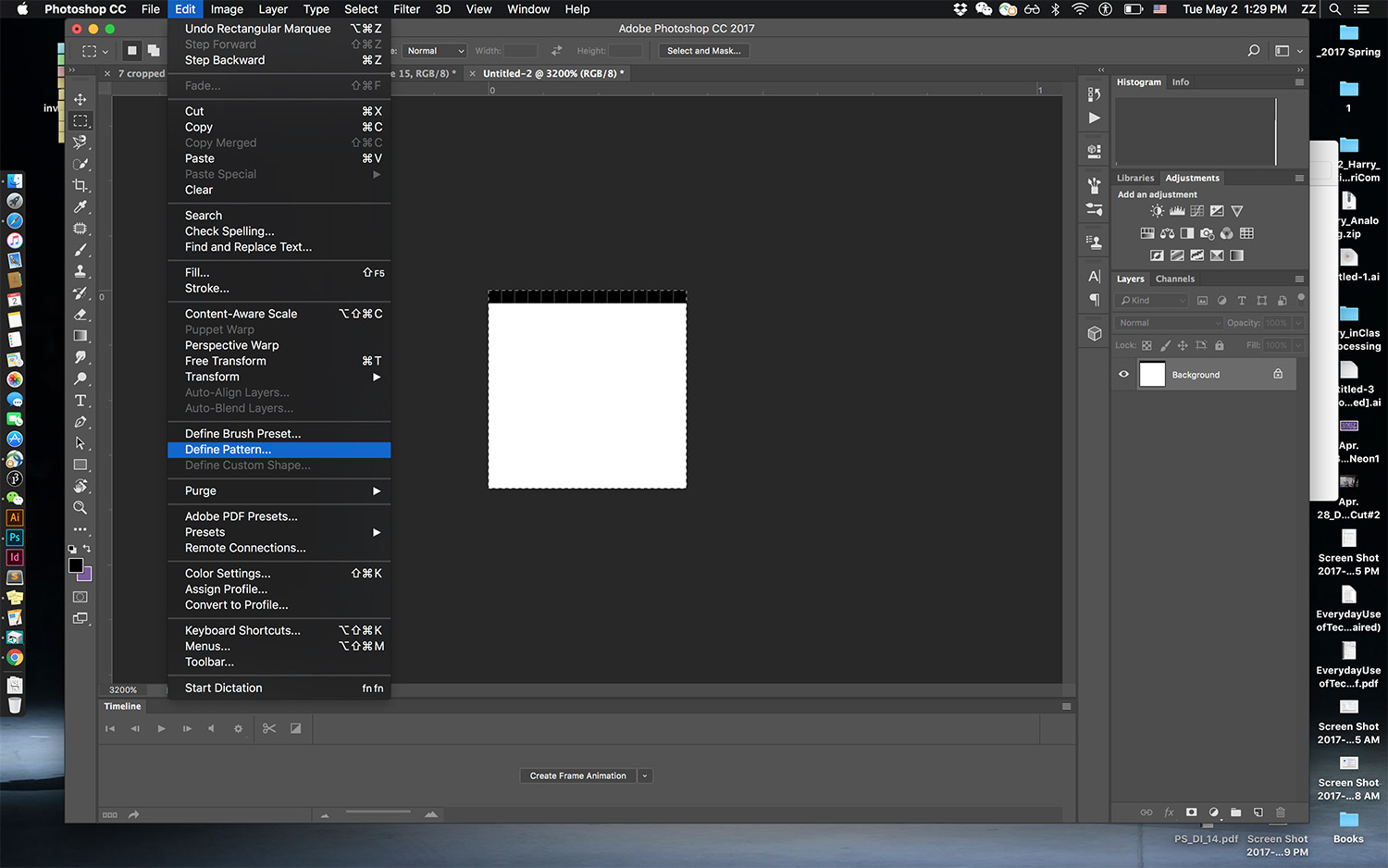
Our “Pattern” is ready: “Select All”, in the menu; choose “Edit”–> “Define Pattern” and save this with a name like “xyz.xyz LPI xyz frames” In my case, “70.23LPI 15 frames”
-
Go back to the final printing file, create a new layer and fill it with the pattern we just defined ”Select”–> ”All”
-
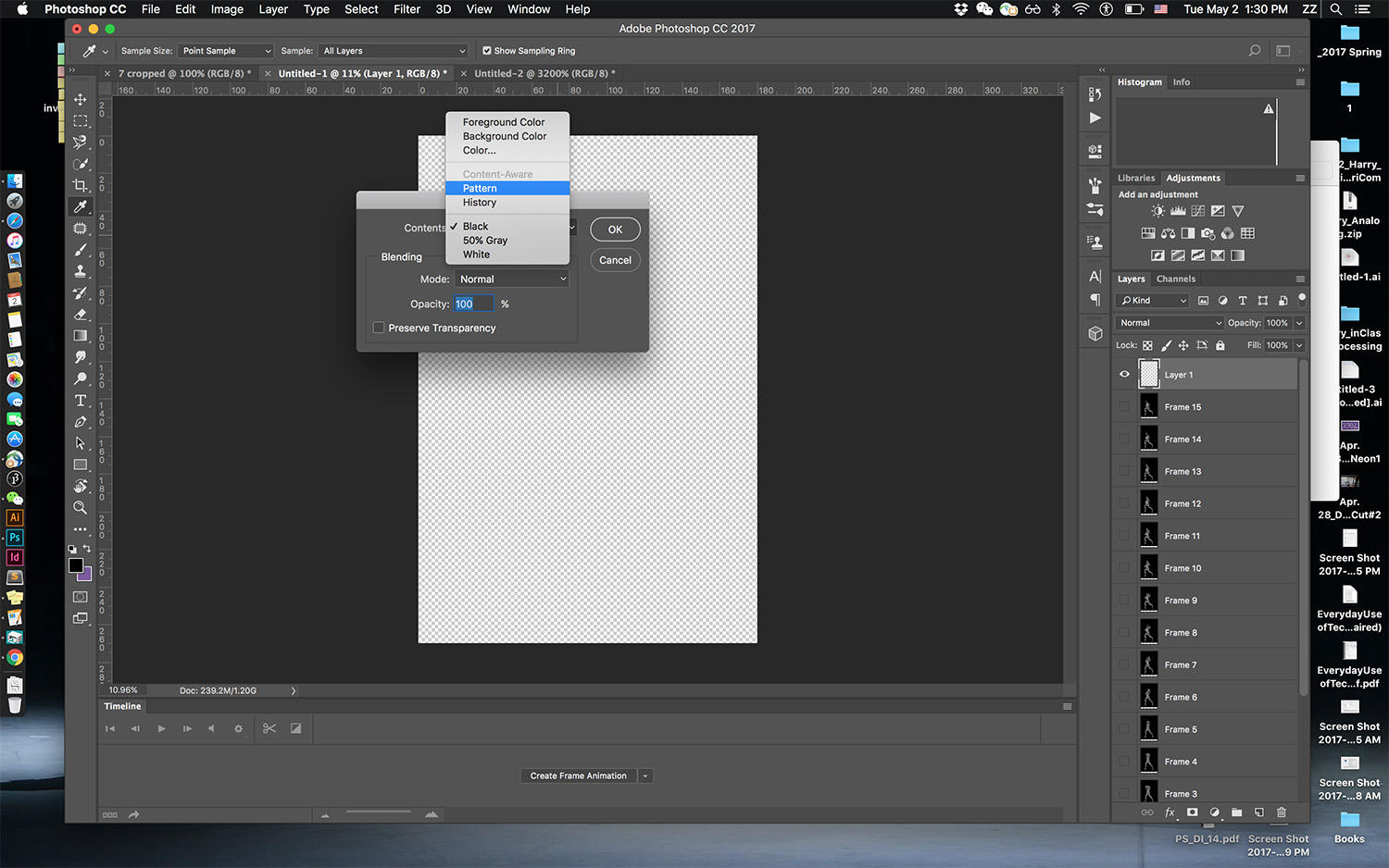
Then in menu again: “Edit” –> ”Fill” for “Content” choose “Pattern” and choose the pattern you just made. This will fill the layer with the selected pattern
-
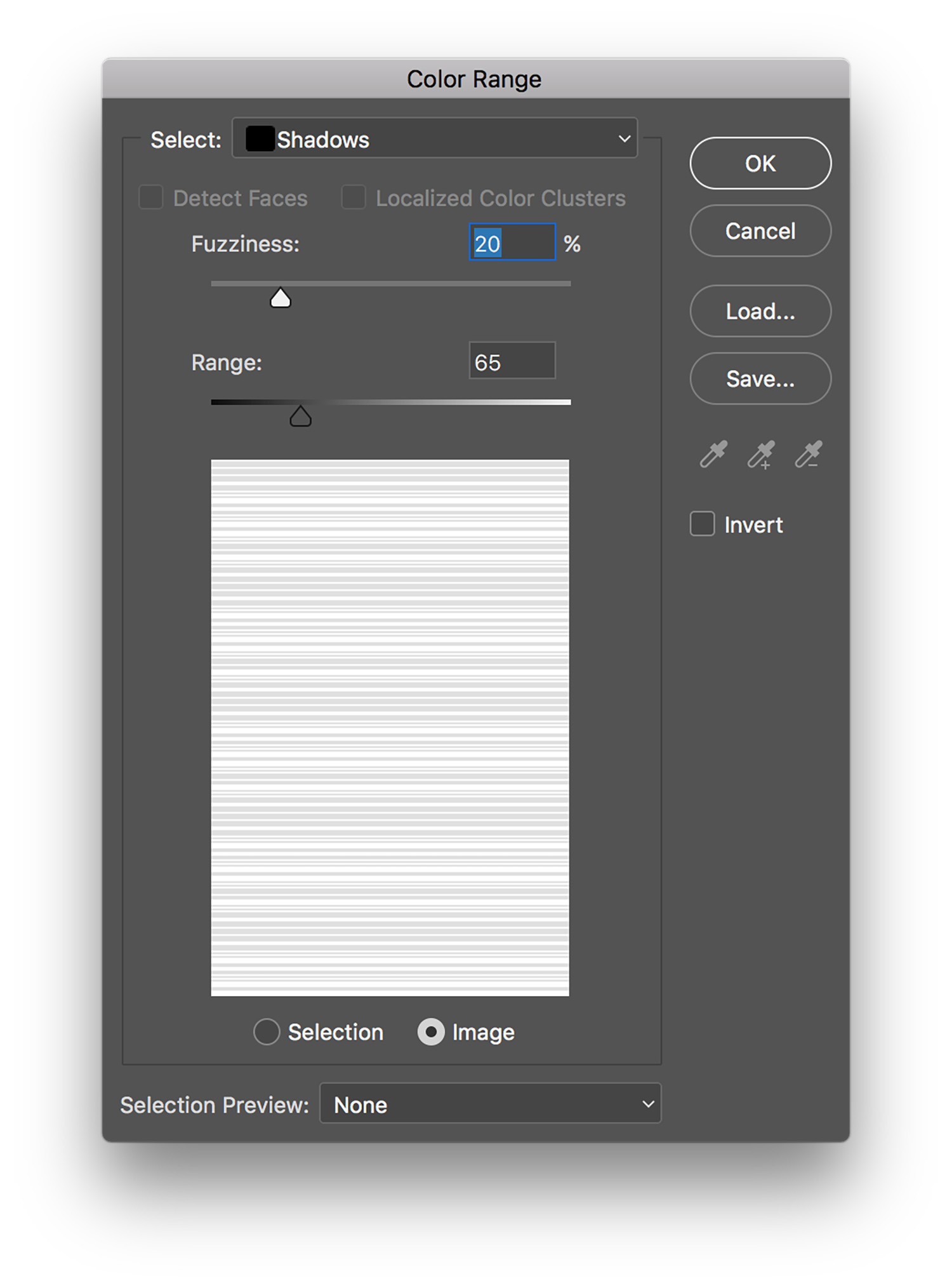
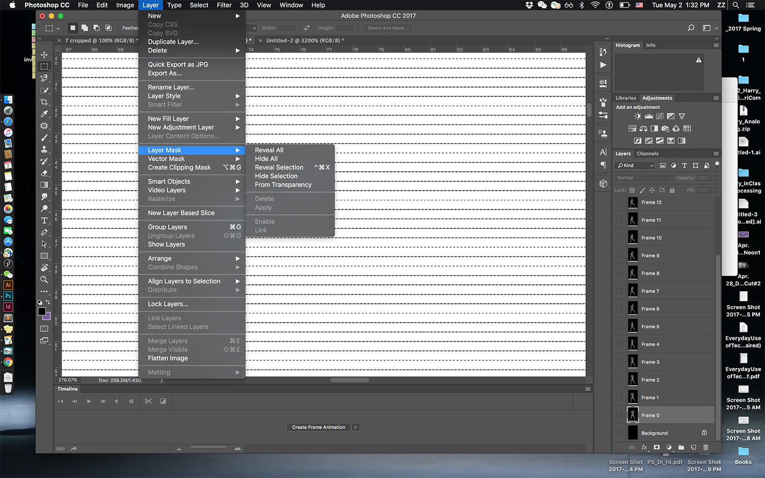
Turn this grid into a selection: in the menu “Selection” –> “Color Range” select “Shadows”
-
This will select the black lines
-
Go to your first “Layer”; in the menu “Layer” –> “Layer Mask” –> “Reveal Selection”
-
This will reveal the image information sitting behind the selection (in my case 1/15 of the image)
-
Go back to your layer “pattern mask” and move it for one pixel (in my case, one pixel down) and repeat the previous step on the second image layer. (In my case, this will reveal 1/15 of the second frame, and filling 2/15 of the final printing image)
-
Repeat the previous step till the final printing image is filled with 1/(number of frames) (1/15 in my case) of each frame
-
Flatten your result and it is ready to output/print
Printing
-
Ink printer is recommended, and photopaper can make the effect look better.
-
Laser printer would work too, but paper options that are compatible are more limited. Ink might not be able to stay well on the paper.